Mesh Capture Tool
Overview
This guide walks a new user through the Mesh Capture Tool.
The Mesh Capture Tool is a Unity extension that serves as an entry point to data compression for some external formats. It includes a Unity scene to capture mesh and texture data so it may be properly ingested by HoloEdit, as well as tools for subtracting geometry from portions of a clip.
The Mesh Capture Tool is captures .4DS files and mesh and texture sequences using OBJ or PLY mesh formats and PNG or JPEG texture formats.
Important
The Mesh Capture Tool supports Unity version 2018.4(LTS). Ensure your Unity layout has both the Scene and Game windows visible when working with the Mesh Capture tool.
Step 1: Data Import and Set Up
You can open the Mesh Capture Tool by adding a new project in Unity Hub and selecting the Mesh Capture Tool folder from your HoloSuite 2021.2 install directory.
Source data, like .4DS files, intended for capture must be placed inside of the StreamingAssets folder in the Unity Project.
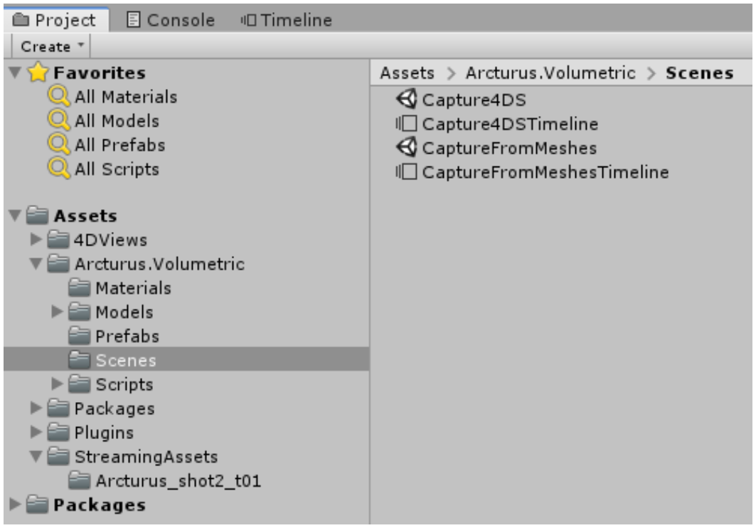
The Scenes subfolder (nested inside Arcturus.Volumetric) includes ready-made scenes to extract mesh and texture information that can be used with HoloEdit. Select either the Capture4DS or CaptureFromMeshes scene.
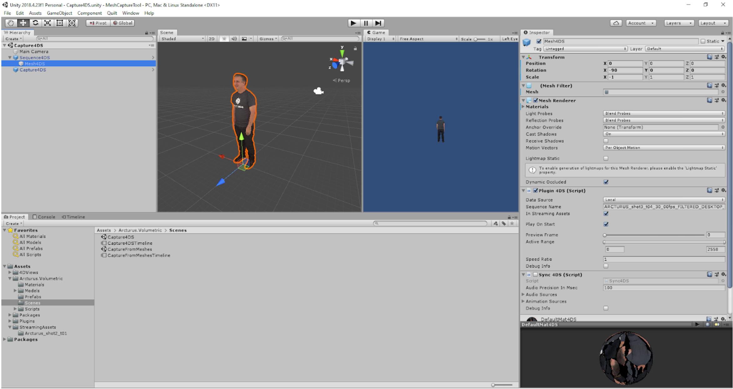
The above screenshot displays an open Capture4DS scene with the Mesh4DS object configured to display a .4Ds file in Unity’s Scene and Game windows.
Step 2: Select Capture Scene
Depending on your input data, you should open either the Capture4DS scene (if your data is in .4DS format) or the CaptureFromMeshes scene (if your data is in mesh + texture sequence format.)
The Capture4DS Scene
Before starting the capture process in a Capture4DS scene, create a new folder in StreamingAssets and copy all of your source data (.4ds files) into it. Name the new folder appropriately so that you can easily identify it later.
The Capture4DS scene contains the following GameObjects:
A Sequence4DS object
A Mesh 4DS object parented to Sequence4DS
A Capture 4DS object.
Each object has specific components that must be configured to properly capture mesh and texture data from a clip.
First, configure the Mesh 4DS object’s components.
Ensure that Play on Start is enabled in the Plugin 4DS component.
The PlugIn 4DS component also has a Sequence Name field. To specify a sequence, drag in your 4ds source data from the StreamingAssets folder.
The Preview Frame slider allows you to scrub through the specified sequence.
The Sequence 4DS object contains Playable Director and Animator components. Ensure that Play on Awake is enabled in the Playable Director component, and that the Playable field is set to Capture4DSTimeline (TimelineAsset).
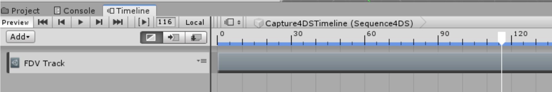
Open the Unity Timeline and select the Sequence 4DS to expose an existing FDV Track.
Important
If you do not see an existing FDV Track in the Timeline, ensure the FDV Plugin and Capture Tool boxes are populated properly with the Mesh4DS and Capture4DS GameObjects.
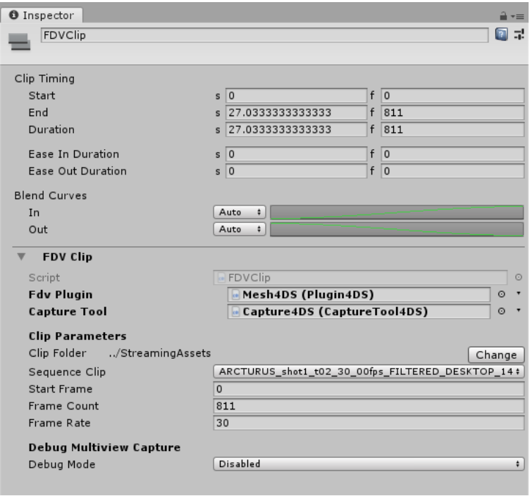
Clicking on the shaded FDV Track in the Timeline window allows you to configure important clip parameters like start and frame information, use the Sequence Clip drop down menu to assign your clip, and view your clip’s total frame count.
Additionally, the Timeline Settings dropdown allows you to specify a frame rate for your clip.
Warning
Currently the only supported framerate is 30 frames per second.
Finally, configure the Capture4DS object.
Note
Capture4DS should be the last object you configure when working in a Capture4DS scene.
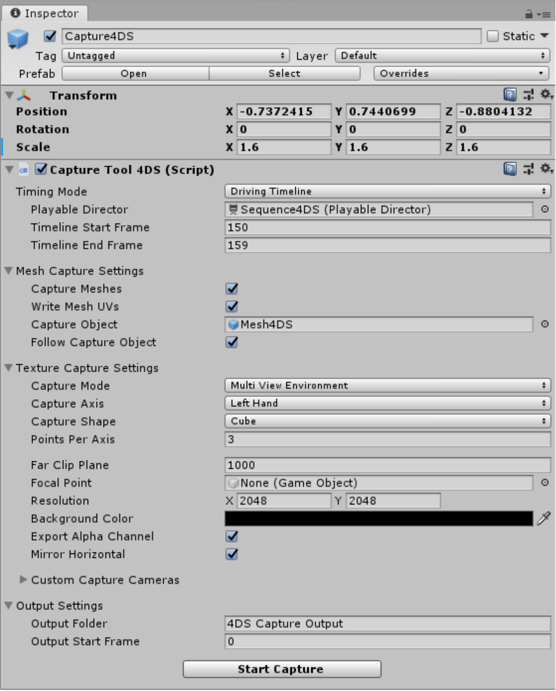
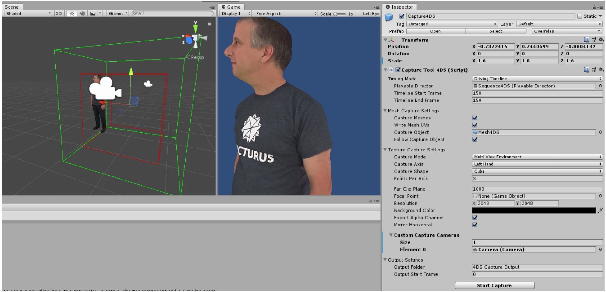
Selecting the Capture4DS object will expose the Capture Tool 4DS component.
Use the Timeline Start Frame and Timeline End Frame fields to specify the capture frame range. You can capture your entire clip by specifying the first and last frames of the clip, or set a custom start and end point to capture a smaller portion.
The Mesh Capture Settings category provides options to include mesh and UV information in the capture process.
Typically, you should enable both Capture Meshes and Write Mesh UVs to ensure you have a complete capture with data that is ready for editing in HoloEdit.
Next, configure the Texture Capture Settings.
Selecting the correct Texture Capture Mode depends on your capture requirements. The three options available in the Texture Capture Mode drop down are:
Disabled: Do not capture textures
Capture Main Texture: This option extracts the source textures from each mesh. This is recommended for most clips.
Multi View Environment: Generates MVE capture data for the selected clip. Select this if you are intending to use a Texture Reconstruction Stage inside of HoloEdit to generate your textures. Here you can configure Points Per Axis for how many cameras are used in constructing the MVE capture array, Resolution, and Export Alpha Channel and Mirror Horizontal which should both be enabled in most cases.
Use the Output Start Frame field to specify a start frame for capturing meshes. To start at the beginning of your clip, enter the number ‘0’.
Now that you have finished configuring your scene, press ‘Play’ in Unity to initiate the capture process.
You will see your sequence start.
Note
After pressing play, your sequence should play back and begin to capture frame by frame. If the Timeline doesn’t advance, ensure that your Unity layout has both the Scene and Game windows visible.
CaptureFromMeshes Scene
Before starting the capture process in a Capture4DS scene, create a new folder in StreamingAssets and copy all of your source data (mesh and texture files) into it. Name the new folder appropriately so that you can easily identify it later.
The CaptureFromMeshes scene contains the following GameObjects:
A CaptureFromMeshes object
a MeshPlayer object parented to CaptureFromMeshes
A CaptureMesh object parented to CaptureFromMeshes.
Each object has specific fields to configure to properly capture mesh and texture data from an asset.
The CaptureFromMeshes GameObject holds Playable Director and Animator components. To edit the included animation, open the Unity Timeline with the CaptureFromMeshes object selected.
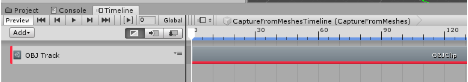
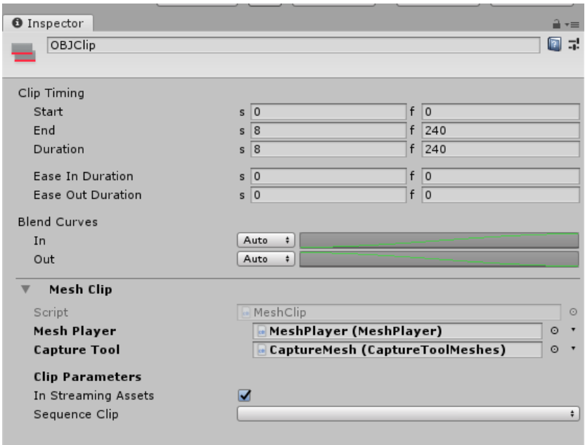
An existing OBJ Track will be present. By clicking on the shaded OBJClip bar, you will see the Inspector window update with Clip Timing and Mesh Clip components to configure. Here, you will need to:
Set the Duration (frames) to one less than the total number of OBJs (i.e. 199 if 200 OBJs),
Verify that the OBJ Player and Capture Tool boxes are populated with the OBJPlayer and CaptureMesh game objects, respectively,
Ensure the “In Streaming Assets” option is enabled,
Select the appropriate Sequence Clip from the drop-down,
Set the Start Frame and Frame Count to match the values in Clip Timing,
Set the Frame Rate to 30
With the MeshPlayer object selected, perform the following:
Ensure that scale on the X axis is negative,
Verify that the Mesh Player (Script)’s Capture Tool field is set to CaptureMesh (CaptureToolMesh),
Set the Frame Rate to 30
Warning
Currently the only supported framerate is 30 frames per second.
You should be able to confirm that your clip is visible in the Scene Window. If it isn’t visible, hitting ‘F’ will frame the object–this may reveal the meshes are much larger than expected. If this is the case, change the scale of the MeshPlayer until it fits in the CaptureMesh box. Values between 0.01 and 0.001 are a good starting point for typical .OBJ files. Note that the CaptureMesh box will only be displayed if the Capture Mode is set to Multi View Environment.
Finally, configure the CaptureMesh object.
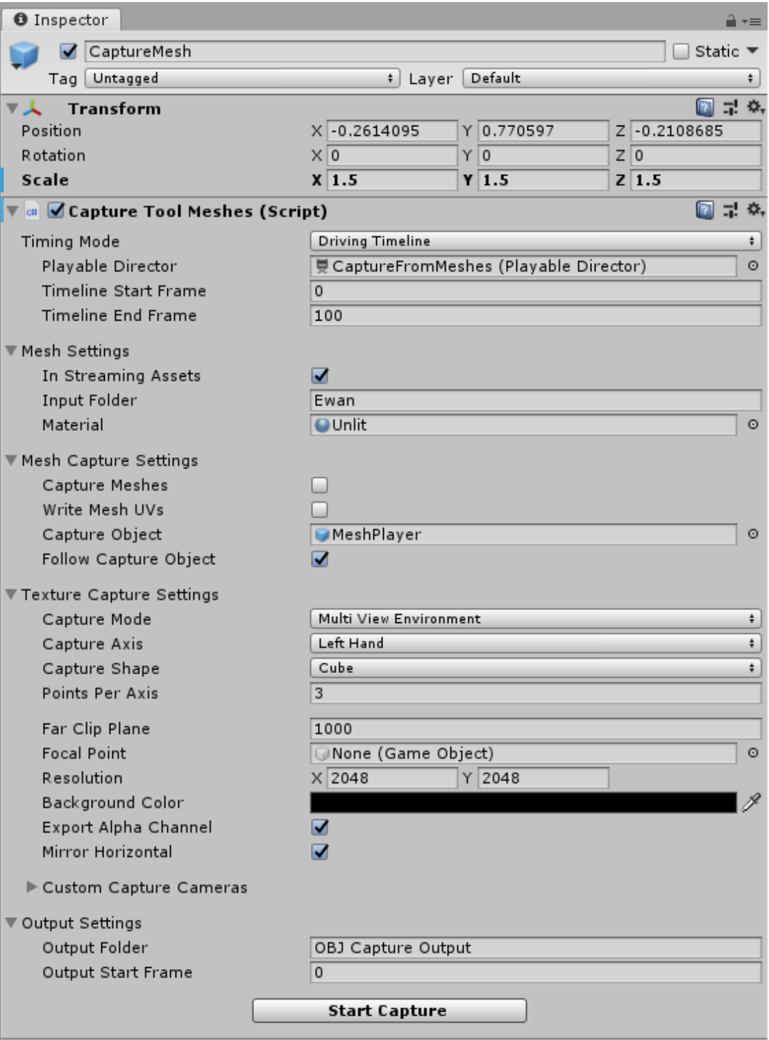
Selecting the CaptureMesh object will expose the Capture Tool Meshes component.
Use the Timeline Start Frame and Timeline End Frame fields to specify the capture frame range. You can capture your entire clip by specifying the first and last frames of the clip, or set a custom start and end point to capture a smaller portion.
The Mesh Settings drawer contains fields that must be filled out to specify your source data for the capture.
Ensure that the In Streaming Assets setting is enabled, then enter the name of your source data sub folder into the Input Folder field.
Note
The “Input Folder” setting is a relative path with respects to the “StreamingAssets” folder. If your data was located in a directory at StreamingAssets/mydata/myclip, you’d enter “mydata/myclip” to specify that folder.
Use the Material field to elect the Unlit material if the data you are capturing from uses textures, or Vertex Color if you need to capture vertex color information.
Inside the Mesh Capture Settings, category, you can enable the Capture Meshes setting to instruct the Mesh Capture Tool to capture geometry. Because you already have the meshes that you’re capturing from, you should typically disable Capture Meshes unless:
The meshes need to be re-scaled,
The subtraction workflow is going to be performed on the meshes
Enable Write Mesh UVs if you have enabled Capture Meshes. Follow Capture Object should be enabled if you are intending on using an MVE texture capture and wish to center the capture.
Selecting the correct Texture Capture Mode depends on your capture requirements. The three options available in the Texture Capture Mode drop down are:
Disabled: Do not capture textures
Capture Main Texture: This option extracts the source textures from each mesh. This is recommended if you’re capturing meshes, rather than capturing MVEs for use with Texture Reconstruction.
Multi View Environment: Generates MVE capture data for the selected clip. Select this if you are intending to use a Texture Reconstruction Stage inside of HoloEdit to generate your textures. Here you can configure Points Per Axis for how many cameras are used in constructing the MVE capture array, Resolution, and Export Alpha Channel and Mirror Horizontal which should both be enabled in most cases.
Click ‘Play’ in Unity to initiate the capture process. You will see your sequence start. If the Timeline doesn’t advance, ensure that your Unity layout has both the Scene and Game windows visible.
3. Output
Once the capture process is initiated in either scene, the Mesh Capture Tool will export your captured clip data. Inside the Mesh Capture Tool directory, the Export folder will begin to be populated with the following:
A new output folder for the capture scene you are using,
A subfolder, timestamped to when you initiated the capture process for easy tracking,
Mesh and/or texture data folders from the designated capture
Subtraction Workflow
In addition to captureing MVEs, you can use the Mesh Capture Tool to add subtractive volumes to remove unwanted geometry from a volumetric capture. Subtractive volumes are objects that will remove all vertices they overlap from the capture. Subtractive volumes can be used for removing small props consistent noise from a clip.
You should create a duplicate scene before beginning any subtraction work. To do this, it is recommended you:
Create a new folder in Assets for your current project or clip,
From your mesh capture scene (either the Capture4DS or CaptureFromMeshes scenes, depending on your source data), use Save As to create a scene file in your new folder.
Next, from the Project Window, right click inside your new folder and create a new Timeline object.
In your new scene, select either the Sequence4DS or CaptureFromMeshes game object and update your Playable Director’s “Playable” field by opening its drop down menu and selecting your new Timeline object.
You’ll need to create either a new FDV Track (for 4DS) or a new OBJ Track (for OBJ) depending on the capture scene you are using, as well as a new FDVClip or OBJClip within the Timeline.
Adding Subtractive Volumes
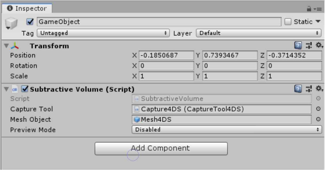
To add a Subtractive volume, Create a new GameObject and add a Subtractive Volume component to it. Make sure that the Capture Tool and Mesh Object fields are populated appropriately for your scene (e.g. Capture4DS (CaptureTool4DS) and Mesh4DS when in a Capture4DS scene).
Subtractive Volumes can be animated, using Unity’s keyframing tools. You can create a Track in the same Timeline that will drive your playback, and these volumes can be previewed using the Preview Mode drop-down in the component. Preview Mode provides the following options:
Single: Will preview only the current volume’s impact
Hierarchy: Will display the impact of the current volume and all its children
All: Will display the impact of all subtractive volumes
Once your subtractive volumes are configured and animated in the Timeline, the normal mesh capture process can be initiated and the volumetric subtraction process will be included in the output data.
Adding Custom Cameras
When using either MVE workflow, custom cameras allow for unique, manually positioned views that you can add to cover difficult to capture areas in a clip, or to provide a high resolution image of an important area. All custom cameras will be captured for every frame just like those of the MVE, and will appear in the “views” list for each frame in the Textures folder.
To add a custom camera to an already configured capture scene:
Create a new Camera in the scene Hierarchy and place it as desired (the camera can be animated if needed)
Select the CaptureMesh or Capture4DS GameObject and:
Expand the Custom Capture Cameras section and increase the Size by 1
Drag your new camera into the new Element box