Blend Mesh

Requirements
Input Streams: Two mesh streams, two texture streams
Output Streams: Modified mesh stream, original or modified texture stream
Overview
Note
Blend Mesh uses the stabilization algorithm. For in-depth information on deformation, see the Deformation algorithm page.
The Blend Mesh stage takes the mesh from two source stages and creates a blended result. Textures can either be transferred from the original source stages, or also blended between the two sources.
Two inputs are required for the Blend Mesh stage to process, Source Stage A and Source Stage B. Source Stage A should be higher in the track hierarchy than the stage being used for Source Stage B.
When processing, the Blend Mesh interval will be use the topology from Source Stage A to perform the deformation.
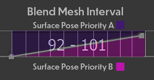
How much each frame should be blended between the surface pose of Source Stage A and Source Stage B is determined by the Blend Curve Shape, Blend Curve Start and End Values. At default settings the first frame of the blend interval will prioritize the surface shape of Source Stage A. Over the course of the Blend Curve it will change from matching the surface of A to a blend of the two surface shapes, finally ending by prioritizing the surface shape of Source Stage B.
When executed Blend Mesh will deform each Source Stage frame, applying the level of interpolation required based off of it’s position along the Blend Curve.
Note
This stage should be run on a cleaned mesh stream, with degenerate triangles fixed, and a polygon count under 100k triangles. Higher triangle counts are supported, but compute hour costs may increase dramatically.
Parameters
Blend Curve Shape: Determines the curve of the pose influence between the blended stages. Where 0 is fully prioritizing the pose of Source Stage A and 1 is fully prioritizing the pose of Source Stage B. Use the dropdown menu to select different curve shapes.
Blend Curve Start: A value between 0 and 1 that determines the weight of importance of the blend source stage pose, where 0 is fully prioritizing Source Stage A’s pose, and 1 is fully prioritizing Source Stage B’s pose. Changing this value will affect the left edge of the blend curve. Default starting value is 0. When an interval containing a blend curve is cut using the Razor tool the values within the new intervals will automatically update to preserve the original blend curve.
Blend Curve End: A value between 0 and 1 that determines the weight of importance of the blend source stage pose, where 0 is fully prioritizing Source Stage A’s pose, and 1 is fully prioritizing Source Stage B’s pose. Changing this value will affect the right edge of the blend curve. Default starting value is 1. When an interval containing a blend curve is cut using the Razor tool the values within the new intervals will automatically update to preserve the original blend curve.
Texture Blend Mode: Select texture processes for blend from None (default) and Cross-fade
None directly passes the original textures from the source stage whose topology is being used as the base mesh for the blend’s deformation. This transfer method should be used in most cases.
Cross-fade performs a closest point texture transfer for each of the two surfaces. The two textures are then overlaid and blended based on the frame’s position in the blend curve.
Deformer Select which deformer will be used
NDP NDP stands for Neural Deformation Pyramid and is the default blend deformer. It uses a hierarchical approach to decompose complex deformations into a sequence of simpler transformations and optimizes them using a combination of cost functions. This deformer is better at capturing non-rigid deformations
ICP ICP stands for Iterative Closest Point and is the deformer used in the stabilize mesh stage. It’s an iterative process that starts with an initial guess for the transformation, and each iteration finds the closest points on the source object to the target object. It then computes a transformation that minimizes the distance between these closest points. This transformation is applied to the source object, and the process is repeated. While in most cases the NDP deformer is better at creating blends, for some data sources the ICP deformer may get better results.
Source Stage A: Click and drag a stage from the current track into this field to use as the first source stage used for the blend.
Source Stage B: Click and drag a stage from the current track into this field to use as the second source stage used for the blend.
Working with Blend Mesh
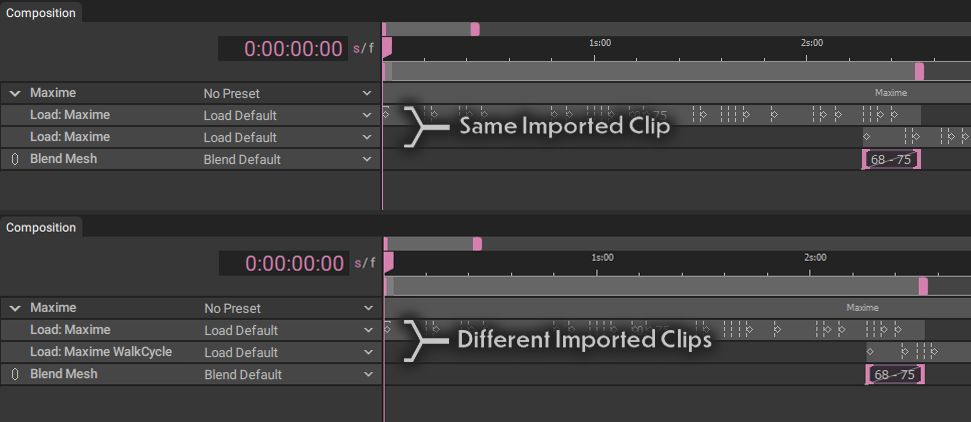
The Blend Mesh stage requires two input stages to blend between. These inputs can be from the same clip imported into the composition twice or two different clips, each imported into the same composition.
The Blend Mesh stage combines the two source stages using the same deformation algorithm as the Stabilize Mesh and Match Template Mesh stages. For More information, please review the Deformation Algorithm documentation.
Mesh samples being blended should be processed first using the Clean Mesh stage to avoid risk of deformation failures while blending.
It’s important to consider the clips being blended and what the most natural place to blend them is. Algorithmic mesh blending is not performed the same way an actor would naturally change poses; matching key limb positions, body position, posing and timing are all important considerations that should be taken into account when blending or looping clips.
Aligning foot positions in a separate track before processing can help prevent your capture from feeling ungrounded or floaty during a blend. Planning so that the general movement between the source stages’ is going in parallel directions will help achieve a more natural flow. Ensuing there is no crossing or overlapping movement in the limbs will help prevent confusing results or loss of details in important areas.
Once you’ve found the portions of frames that will be blended create the Blend Mesh stage, then create an interval containing the frame range you will be blending.

With the Blend Mesh stage selected and the Inspector panel open, click and drag the stage containing the mesh stream (that will lead into your blend) into the Source Stage A field, next click and drag the stage containing the mesh stream (that will lead out of your blend) into the Source Stage B field.
Make adjustments to the stabilization parameters as needed per your specific data.
Textures with the Blend Mesh stage have two options: None and Cross-fade. In most cases we suggest using ‘None’ as there is significant risk of ghosting overlap of the blended textures with the cross-fade method. None will apply the existing textures from the source stages. Cross-fade texture blend mode works best in the case of a transition between two widely different clips where a single frame transition of textures would be more obvious.